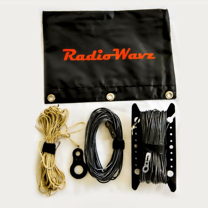
The RW705 QRP antenna system has been designed and optimized to be used with the ICOM AH-705 auto coupler, providing broadband HF operations over the most diverse environments.
Features:
- Single wire stranded insulated 33 ft. 3.5-50mHz (66-foot and 92-foot radiators optional)
- 100 Watts • Multi length counterpoise. Optimized for 40m, 20m, and 10m.
- Wire winder designed with mobile operations in mind.
- Figure 8 support. Allows for dynamic installation.
- Portable carrying pouch.
- 25 feet support line. (Non-wicking 200lb)
The rugged, ultra-portable, and lightweight RW705 antenna system has been designed with QRP operations in mind. It is easily deployed with multiple configurations to meet operational demands. This is an end-fed antenna.
Operation:
1: Remove the Antenna and Counterpoise from the pouch.
2: Unwind the counterpoise wire set. Place it next to the antenna coupler.
3: Determine the configuration of the antenna e.g., horizontal, vertical, inverted V, sloped.
A: For inverted V or L operations, use the Figure 8 support insulator to suspend the middle of the wire. Configure the radiator wire for the desired operation. Place the counterpoise wires on the ground stretched out into the appropriate configuration. Use the end insulators to secure the ends of both the radiator wire and counterpoise.
4: Connect the radiator wire to the transmit Lug on the auto coupler.
5: Connect the counterpoise to the ground lug of the auto coupler.
6: Ensure the Antenna System is in a safe and secure condition.
7: Follow equipment operational configurations recommended by the manufacturer.
8: To recover the antenna after use.
A: Disconnect the radiator and the counterpoise from the auto coupler.
B: Lay all the wires and support lines on the ground.
C: Secure the radiator first to the winder.
D: Wind up the radiator wire.
E: Secure the counterpoise wires to the winder.
F: Wind up the counterpoise wires.
G: Finally secure the support line.
H: Wind up the support line.
All three components can neatly fit onto the winder. Secure the winder with the tie wraps supplied with the kit.

